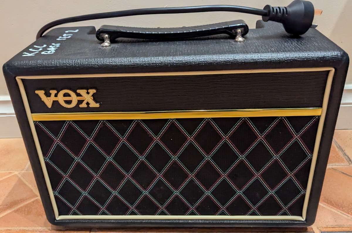
My mate Steve and I both have pieces of paper that say "Batchelor of Electronic Engineering", but neither of us do that for a living. We both however want to be able to say that we can actually work on electronics. For example, a while back I fixed a broken amp. So when a broken Vox Pathfinder Bass 10 fell into my hands I felt compelled to fix it.
I have however come to realise that I will only go so far. If it's not a broken wire, popped fuse or simple power supply issue, then it's going to take too long and I neither have the patience or equipment to really dig in deep. This amp was no simple fix. It had a weird distortion coming through. Steve however, he loves a challenge. And since this is just a little analogue amp, I threw it his way and he persisted until he fixed it.
During the, I'm going to guess hundreds of hours he spent debugging it, he produced an electrical schematic. It needs to be on the internet, so here is a pdf of the electrical schematic and here is a jpg.
A short discourse...it presented with some high mid/high frequency distortion on top of the expected signal. You could set the bass volume and the amp volume to reduce it, and if you played softly it wasn't too bad, but it was always there.
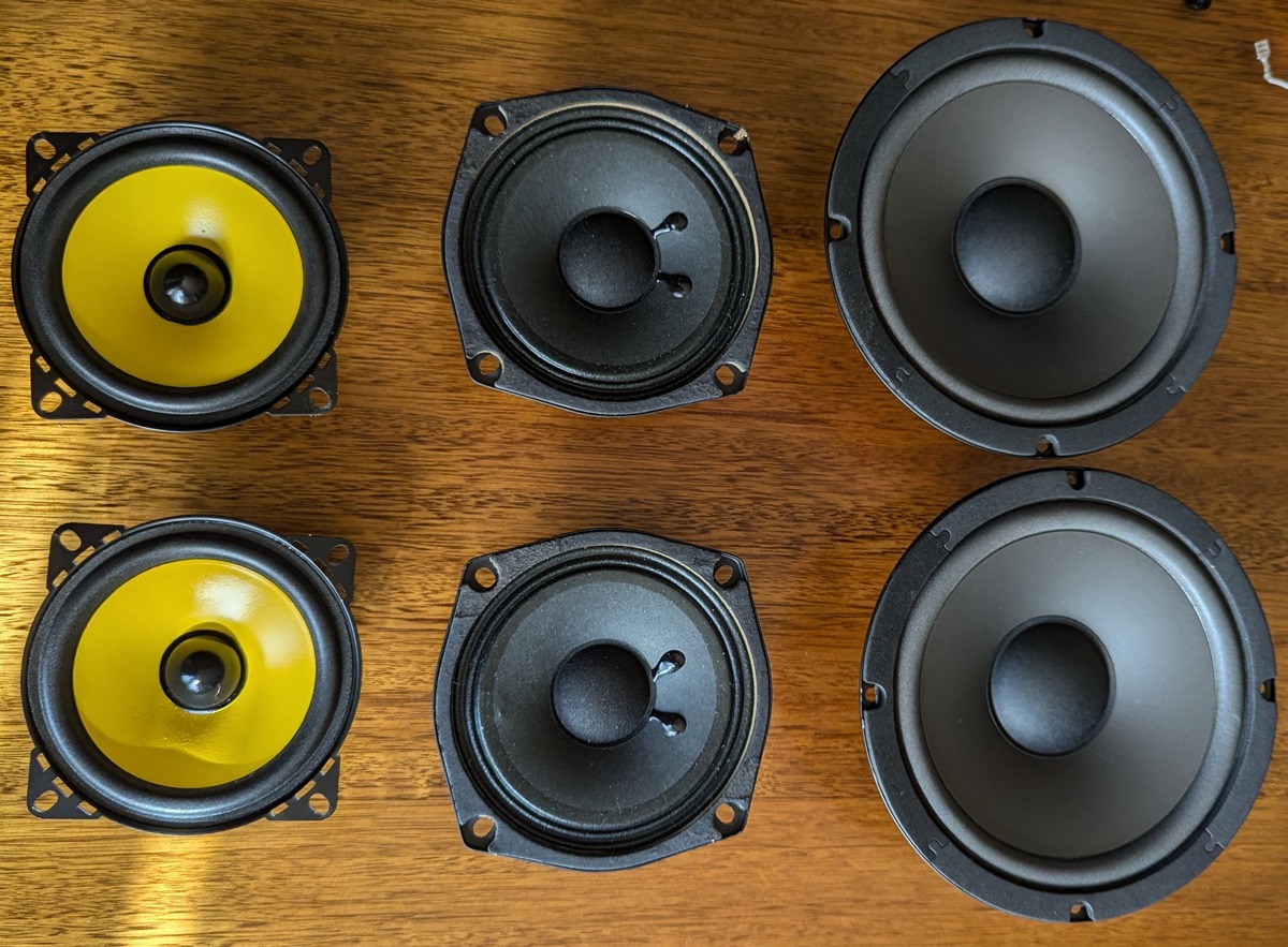
On first inspection Steve discovered a hole in one of the speakers which I hadn't noticed and sent it back. Seemed fair enough, that could cause noise. The speakers in there were a fairly non standard 5", I decided that some cheap 4" speakers from AliExpress would do the job. Put them in, no, distortion still there. and they were pretty rubbish. Without thinkng too hard I grabbed some slightly less cheap 6" speakers, and put them in with some slight hassle (they were a bit big, but I made them fit). Still distorting. I had concluded it wasn't the speakers and sent it back to Steve. He was not convinced and bought some not-so-cheap correctly fitting 5" speakers...still distorting.
During let's call it "the speaker phase" Steve mapped out a frequency response curve of the 4" (YH-1008) and 6" (YH-600) speakers, and for reference the sub speaker from his home theatre system. Remembering that the low E on a bass is around 40Hz you can see that the two cheapy speakers aren't great around there and don't really flatten out frequency reponse wise until over 100Hz. The sub speaker starts flattening out at 50Hz which is better, but we discovered that for bass amp design you really need to think about how you are going to get those low frequencies pumping air.
But the speakers proved to be a red herring.
Steve's equipment was struggling to show the nature of the distortion, which is kinda frustrating "I can hear it, but I can't see it". Looking at a bass guitar signal as it goes through the circuit, we could see that there seemed to be a few pixels of high frequence noise superimposed on sections of the waveform. But neither of us would declare "that was it". Steve, being persistent, then went to town replacing components.
 Signal vs Opamp 1a Signal vs Opamp 1aMaybe noisy? |
 Signal vs Opamp 1b Signal vs Opamp 1bInverted, looks fine! |
 Signal vs Opamp 2 Signal vs Opamp 2Inverted, maybe noisy? |
 Signal vs power Opamp 3 Signal vs power Opamp 3Inverted, DC offset, some noise? |
An interesting part of this amp design is that the power side is an opamp! That is, an Operational Amplifier, which is more of a circuit in a chip than just a transister/FET/tube valve. Opamps are great, because they have a pretty flat frequency response across the full spectrum, super high gain, super high input impedence...I didn't imagine a power opamp would be the power house behind an amp! There are some low power opamps in the circuit too, which are there to handle the overdrive circuit, the treble, mid and bass EQ signal adjustments.
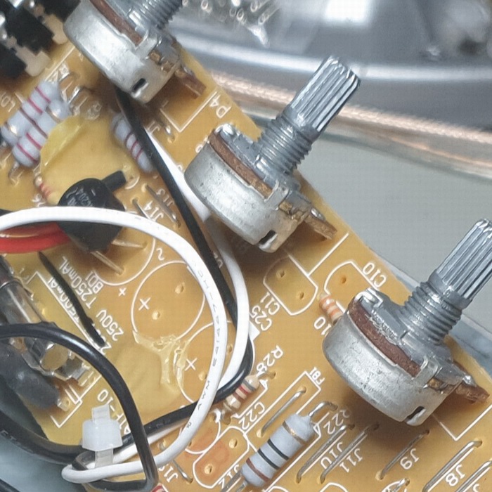
Steve's experience with electronics makes him suspect capacitors every time. Because capacitors fail. He popped every single one of the board, and tested them. None were a problem.
He discovered that although the signal opamps and the power opamps were obsolete, there were equivalent replacements which he also swapped out. It was not a function of the opamp.
At this stage we were both scratching our heads. There wasn't much left to swap out. Something that he had noticed along the way is that the transformer power supply was being pulled down pretty hard, getting close to the minimum operating voltage for the power opamp. While the supply was within spec, after looking at what the opamps can handle voltage wise, he decided to buy a higher voltage transformer with a few more VAs too. The one he selected could fit in, it was right at the upper limit of the opamp capabilities, se he swapped out two resistors to ease back a little on the voltage.
Oh, and he grumbled a lot about the board. How 240VAC was intertwined with signal voltages, how there were so many links on the board and just a generally poor layout of the board, and how difficult it was to pull apart and put back together - that it, like so many things these days, is not designed to be easily serviced. Are you listening Vox?
Well Steve was right. With a new transformer kicking in a bit more juice, the distortion went away. Fixed. My take on this is that the power supply selection is build down to a price, and most of the time, when things are running to specification, it will work. But without a little bit of over-engineering in place, the moment the transformer had dropped a few VAs, some higher frequency weird opamp distortion crept in. Getting those opamps back up to plenty of voltage headspace, problem solved. Vox - spend a bit more money on parts!
 Board Before Board Before |
 Board Modified Board Modified |
Good work Steve! We both learnt something! Oh, and one other very cool thing I learnt - inside the unit were two LEDs back to back. "Why are there LEDs inside the unit, that will never be seen?" After staring at the circuit for a while, working from our electronics first principles knowledge Steve and I realised that as the "drive" level is turned up, the LED foward volt drop, probably around 2V, will start to kick in, which will begin to clip the waveform. As we know, if you raise the amplitude of a signal but then start to clip the peaks, you get both an additional loudness increase, and all those extra harmonics as it clips which brings more complexity to the sound. After reading up about it on the internet, aparently LEDs have quite a sonically pleasing soft-clipping sound rather than the much harder clipping found in other diodes!


